Fysetc Spider v1.1
Wiring
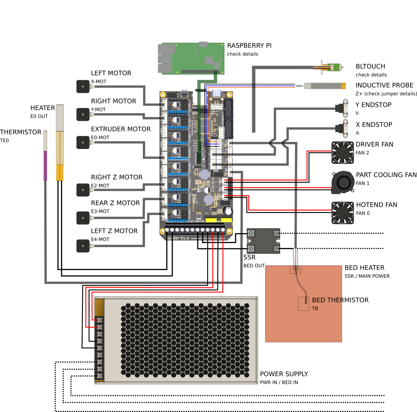
You will probably have to swap the outer two wires (red and white) on the board end of the cable but double check to make sure.
If you have been testing your Spider without the stepper drivers plugged in, there is a chance that you'll blow the 3.3V voltage regulator on the board if you do not discharge the capacitors before connecting the drivers. The lesson here is don't power up the Spider without the stepper drivers plugged in. Please read https://github.com/FYSETC/FYSETC-SPIDER/blob/main/Spider%203.3v%20issue.md
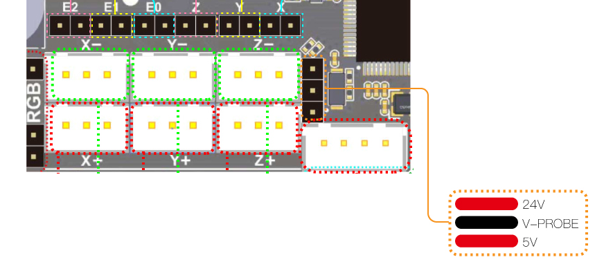
Before connecting a probe check the probe voltage selector jumper.
Connection to your Pi
While the Spider can connect to your Pi via it's UART this is not supported by V-Core OS as standard and will require manual firmware configuration.
The normal V-Core OS connection is via USB as this allows new versions of Klipper to be uploaded without needing an SDCard. You can, of course, power the Pi from your Spider whichever form of connection you use or if you use a dedicated Pi Power Supply you can shut down your Spider while leaving the Pi running.
Firmware installation
For the first time install of Klipper onto the Spider; there are two methods. With an SD Card or via SSH(PuTTY)/USB.
The SD Card method is suggested as being the easiest.
Flash via SD Card (recommended)
Download the firmware-fysetc-spider.bin from the firmware_binaries folder found on the Machine page of Mainsail, copy it onto the SD card that goes into your control board and call it firmware.bin, then insert the SD card in to the control board. Here are the steps in chronological order:
- Navigate to http://RatOS.local/
- Open Machine page
- Open
firmware_binariesfolder - Download
firmware-fysetc-spider.bin - Format the sd card for your board to FAT16 (sometimes just called FAT), or FAT32 with a clustersize of 8kb or 4kb.
- Copy
firmware-fysetc-spider.binonto the sd card for your board - Rename
firmware-fysetc-spider.bintofirmware.bin. Please be wary of file extensions! If the file doesn't already show .bin, don't add it! - Safely eject the SD card through your operating system.
- Physically take out the sd card and insert it into your control board.
- Power cycle your printer or control board. Remember to shut the pi down properly before you cut power to your Pi (you can do that through Mainsail using the dropdown menu in the top right corner). The upload should take a few seconds and a LED by the SDCard slot should flash while this is happening.
- Verify that the firmware has been flashed and Do not put the sd card back in the board after successful flashing.
For more information; this is documented on the Fysetc pages: https://github.com/FYSETC/FYSETC-SPIDER#42-Klipper
If you don't know how to make Windows Explorer show file extensions, see this article on HowToGeek
If you have an ADXL345 connected to your Spider as shown below, you may need to disconnect it from your Spider to avoid conflicts with the SD Card while loading the firmware.
First time flashing via SSH(PuTTY)/USB
While the SD Card method described above is the easiest, users that are comfortable with SSH/PuTTY may prefer this more advanced method.
Fysetc provide instructions on installing Klipper here: https://github.com/FYSETC/FYSETC-SPIDER#42-Klipper but some parts of that are less clear than one might wish so here is the sequence that worked for the author.
Make sure your board is connected to the Pi (USB-C on the Spider, USB-A on the Pi). Connect with SSH (PuTTy for Windows users) to the Pi (login pi, password raspberry if you did not change the defaults).
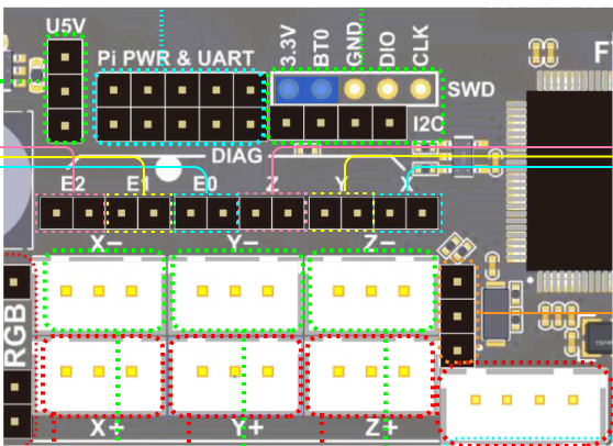
Connect a jumper between 3.3V and BT0 on the Spider as shown above.
Press the reset button on the Spider.
On the Pi, run the following command:
dfu-util --list
You should see a list of DFU devices. This is your Spider ready to have the firmware uploaded.
Build the firmware which is covered here: Manual Firmware Compilation
Once the firmware is built on the Pi run:
sudo service klipper stop dfu-util -a 0 -s 0x08008000:leave -D ~/klipper/out/klipper.bin
You should see the firmware being written to your Spider.
Now remove the jumper between 3.3V and BT0 on the Spider. Press the reset button on the Spider.
Run "lsusb" on the Pi and you should see a device by the name "OpenMoko, Inc.". This is your Spider running Klipper.
run the command "sudo service klipper start". RatOS should now be able to communicate with your Spider.
Klipper Updates
RatOS automatically flashes the newest firmware to your Spider v1.1 when klipper is updated (if the klipper firmware has previously been flashed). You shouldn't need any of the steps below unless that fails.
Sometimes klipper makes changes to the microcontroller code and thus your Spider need to be reflashed with new firmware. You can do that in 2 ways.
The updates can be installed with an SD Card (same method as the first install described above) or over a Pi/Spider USB connection from RatOS using SSH(PuTTY) and the provided ~/klipper_config/config/boards/fysetc-spider/make-and-flash-mcu.sh command so you don't need to fiddle around with SD Cards.
Setup
If you're going through initial setup please continue in the installation guide
ADXL345 Connection
In your printer.cfg uncomment the following:
For ADXL345
[resonance_tester] accel_chip: adxl345
Change the following to the centre of your bed.
probe_points: 200,200,20
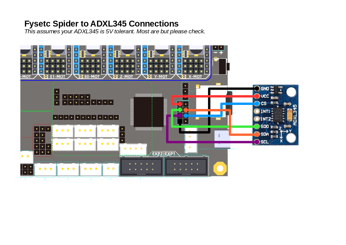
Connect the ADXL345 to the Spider like so:
Spider ADXL345 5V VCC GND GND MISO SDO MOSI SDA SCK SCL CS CS
See the Fysetc wiring plan for details: https://github.com/FYSETC/FYSETC-SPIDER/blob/main/images/Spider_V1.0_Pinout.jpg
You might have to disconnect the ADSL345 from your Spider while you are uploading firmware using the SD Card.
Undervoltage errors
If you are using the Fysetc TMC2209 step-sticks and you're getting Undervoltage errors from the stepper drivers make sure to either fully disable or enable stealthchop.
To completely disable stealthchop add this to the "### USER OVERRIDES" section of printer.cfg for each driver on your printer:
    [tmc2209 stepper_x]
    stealthchop_threshold: 0
You can also enable stealthchop instead, like so:
    [tmc2209 stepper_x]
    stealthchop_threshold: 9999999
Klipper recommends using either stealthchop or spreadcycle for TMC drivers: https://www.klipper3d.org/TMC_Drivers.html